|
1. Single-flute spiral upcut bit
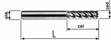
Used for cutting all kinds of soft materials that produce large chips. These bits are designed specifically for high spindle speeds, which ensures fast material processing. The geometry of the spiral flute lets chips clear freely, which keeps the bit well cooled and extends its service life.
2. Single-flute spiral downcut bit
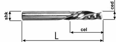
Used mainly for cutting wood to avoid chipping along the cut edges. Downcut bits are also successfully used for cutting plastic, PVC and acrylic on machines without a vacuum hold-down table, because the cut part does not shift and therefore needs no extra fixing with 2-sided tape.
3. Spiral bit with two or more flutes
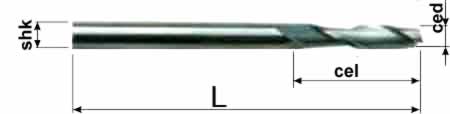
Used for machining that produces finer chips and removes less material per pass. The number of teeth and the flute depth ensure the chips are finer. Bits with more flutes give a cleaner machined surface.
4. Two-flute spiral ball-nose bit
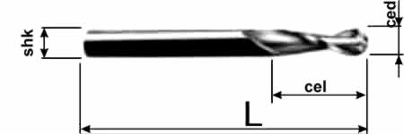
Produces a smoother surface thanks to lower vibration during cutting. This bit is used for U-groove engraving (e.g. text) on the surface of a material, and for finishing or roughing of 3-dimensional objects (depending on the size of the smallest relief details). When used for finishing hardwoods, it leaves a polished surface that needs no further work.
Spiral bits are also used for roughing and finishing (depending on the geometry of the surface being machined) of 3D objects and various shapes.
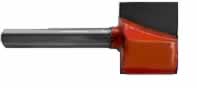
5. Profile (form) bit
Used to make various frames and edgings whose cross-section matches the bit profile.
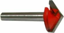
6. V-bit engraver
Used for V-carving, chamfering sharp edges of a material or preparing fold lines on composite materials (although a dedicated V-groove folding bit does this job better).
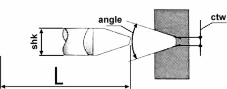
7. Tapered engraving bit
Used for machining small 3D relief details or fine V-carving.
8. Theory of choosing cutting parameters
Spindle speed and feed rate are the basics of cutting. This information is relatively easy to find – any book on milling contains it. Below is a brief summary of one such book. The cutter diameter is chosen based on two parameters: milling width and milling depth.
Milling width is the width of the surface to be machined; it is usually given in the drawing and depends on the size of the part or workpiece. When several workpieces are clamped side by side, the milling width increases accordingly.
Milling depth is the thickness of the material layer removed by the cutter in one pass. If a lot of material needs to be removed, the cutter makes two or more passes. The last pass is made at a small depth of cut to obtain a cleaner surface. This pass is called finishing, as opposed to roughing, which is done at a greater depth of cut. If the machining allowance is small, however, milling is done in a single pass.
Cutting speed is the distance (usually expressed in metres) travelled by the cutting edges of the cutter teeth in one minute. Cutting speed is calculated as follows: multiply the cutter circumference by the number of teeth and by the revolutions per minute, then divide the result by 1000 (to convert millimetres to metres).
![Using milling cutters]()
Accordingly: ![Using milling cutters]()
Cutting speed is usually taken from reference tables of cutting parameters. Since the cutting speed in milling depends on the tool life of the particular cutter, the speed recommended in the tables is the maximum speed at which cutting can be done without breaking the cutter.
Feed is the distance (usually expressed in millimetres) the machine spindle travels in the longitudinal (Y), transverse (X) or vertical (Z) direction.
![Using milling cutters]() Feed per minute is the distance the spindle travels in millimetres in one minute. It is calculated as feed per tooth multiplied by the number of cutter teeth and by the cutter revolutions per minute. Feed per minute is the distance the spindle travels in millimetres in one minute. It is calculated as feed per tooth multiplied by the number of cutter teeth and by the cutter revolutions per minute.
![Using milling cutters]() – this is an excellent starting value for machining difficult materials. – this is an excellent starting value for machining difficult materials.
![Using milling cutters]() This feed should be increased or decreased depending on the results achieved in practice, but it must stay within the following range: This feed should be increased or decreased depending on the results achieved in practice, but it must stay within the following range:
where D is the nominal cutter diameter.
Milling procedure
- The cutting speed and feed per minute are determined from the cutter diameter, milling width, depth of cut and feed per tooth. The specific conditions of each job must be taken into account: whether coolant is used, the cutter design, etc.
- Set the spindle speed.
- Set the spindle feed rate.
Tool wear
The higher the cutting speed, the more heat is generated and the hotter the cutter teeth become. At a certain temperature the cutting edge loses its hardness and the cutter stops cutting. This temperature differs between cutters and depends on the material the cutter is made of.
A cutter becomes blunt during use. Blunting is caused by wear resulting from friction of the outgoing chips against the rake face of the tooth and friction of the tooth flank against the machined surface. Friction also raises the temperature of the cutting tool, which in turn reduces the hardness of its edge and accelerates wear. During use, a cutter goes through three stages of wear:
- New, sharp cutter – fit for use.
Signs: factory lubricant present, normal surface colour (no scale), even original sharpening.
- Cutter with normal wear – further use is inefficient; it is better to resharpen it.
Signs: vibration, an uneven (torn) machined surface and excessive heating due to increased friction.
- Cutter with catastrophic wear – the cutter practically cannot be restored.
Signs: the cutting edge is visibly destroyed.
|
 for machining metals and other engineering materials by cutting (milling). By type (purpose), cutters are divided into plain (cylindrical), face, side-and-face slotting (single-, double- and three-sided), slitting (slotting) saws, end mills, keyseat cutters, T-slot cutters, angle cutters, form cutters (including disc-type and end-type gear cutters) and hobs; by tooth section – profile-sharpened and form-relieved; by tooth shape – with straight, helical or staggered teeth; by helix direction – with right-hand or left-hand flutes; by design – solid, composite, assembled, with inserted teeth (blades) and gang cutters; by mounting method – arbor-mounted (shell) and shank-type (taper or straight shank); by cutting-edge material – high-speed steel, cemented carbide and composite materials.

 Feed per minute is the distance the spindle travels in millimetres in one minute. It is calculated as feed per tooth multiplied by the number of cutter teeth and by the cutter revolutions per minute.
 – this is an excellent starting value for machining difficult materials.
 This feed should be increased or decreased depending on the results achieved in practice, but it must stay within the following range:


 About us
  Company documents
  Contacts
  Payment
  DELIVERY
  Gallery
  For designers
  Print-ready artwork requirements
  Aluminium composite colour range
  Chipboard colour palette in stock
  Artwork approval rules
  LED neon colours
  Artwork design
  RAL colour chart
  Pantone colour chart
  Series 641 – economy
  Altuglas coloured acrylic palette
  Two-layer plastic colour palette
  Useful articles about advertising